| Wafer size: | up to 6" |
| Frame size: | Ø6" DTF 2-6-1 |
| Width: | 473 mm |
| Depth: | 885 mm, (1042 mm with PTW) |
| Height: | 630 mm |
| Weight: | 130 kg, (145 kg with PTW) |
| Vacuum required: | -70 kPa (-525 Torr), Ø6 mm |
| Pressure required: | 6 bar (87 psi), Ø6 mm |
| Power input: | 110-240 VAC |
| Certification: | CE Certified |
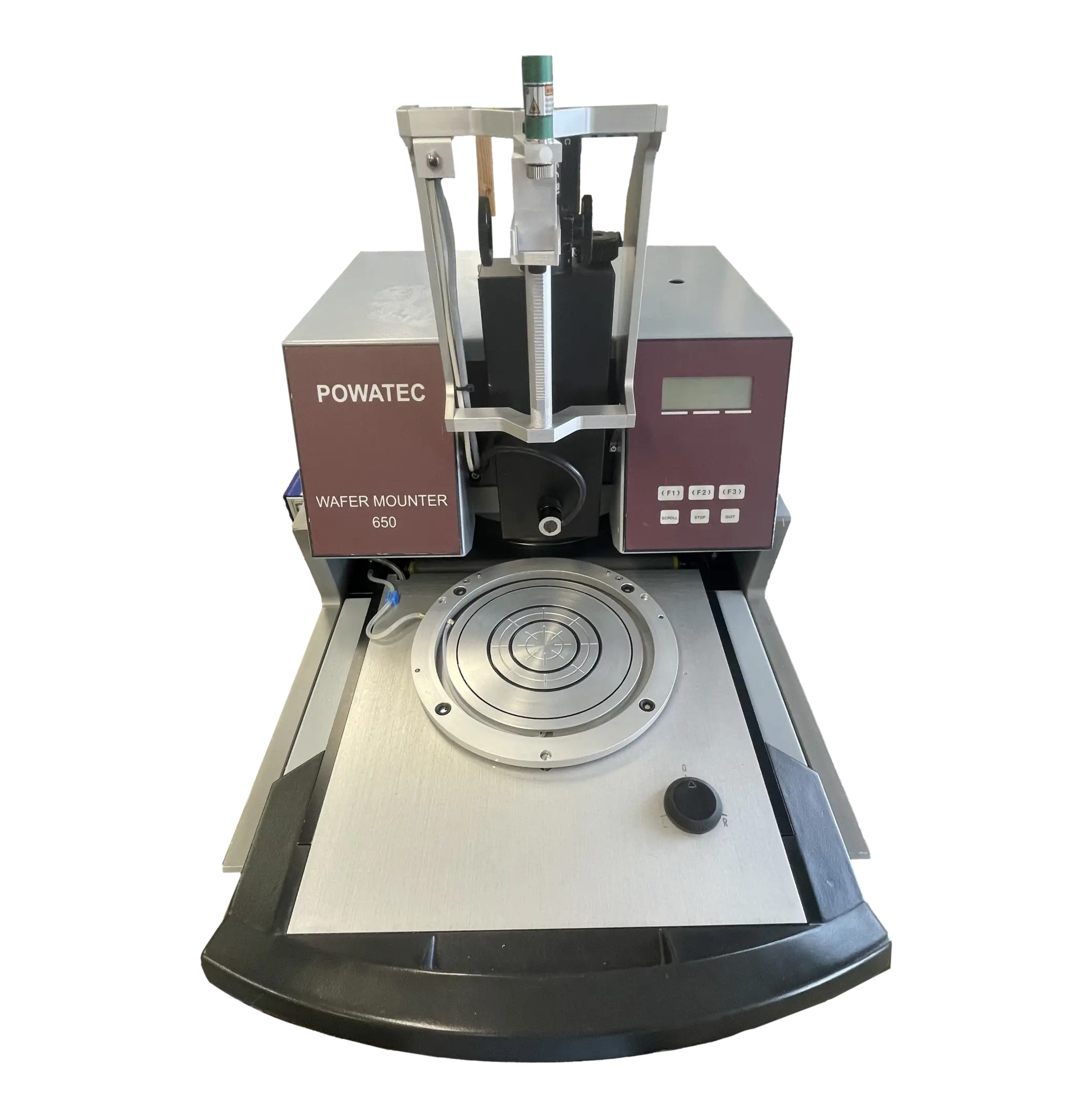
Manufactured and developed in Switzerland, the Automated Gallium Arsenide Wafer Mounter WM-650 GaAs from Powatec is the ideal solution for precisely and reliably mounting 6-inch Gallium Arsenide wafers onto commercially available dicing tapes and frames.
This variant of the WM-650, which has been an industry standard for over 25 years, is adapted to accept Gallium Arsenide wafers, but also any other fragile, ultrathin, warped, or broken wafers mounted on Gel-Pak carriers.
Process Steps
The frame is placed on the loading table followed by the Gallium Arsenide wafer on a Gel-Pak.
A laser overlay assists the user to center the wafer, and the splitfield optic monitor allows the user to align the x-axis, y-axis, and theta of the wafer relative to the frame without ever having to touch the wafer itself.
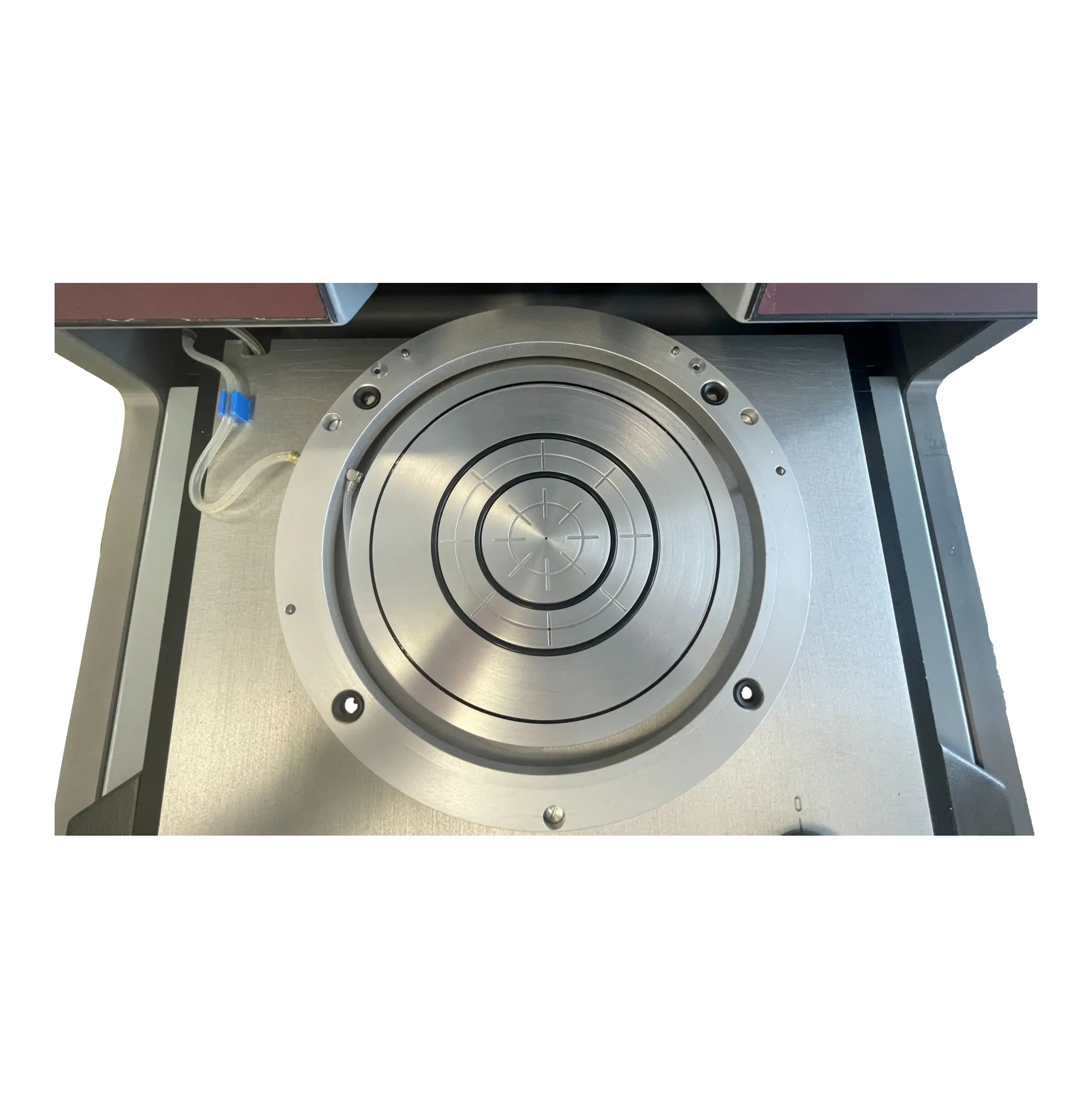
The wafer and frame are then moved into the device where a vacuum chuck fitted with a protective carbon tissue securely removes the wafer and frame from the loading table and holds them in the upper chamber by preventing any lateral movement between the sensitive active wafer surface and the chuck.
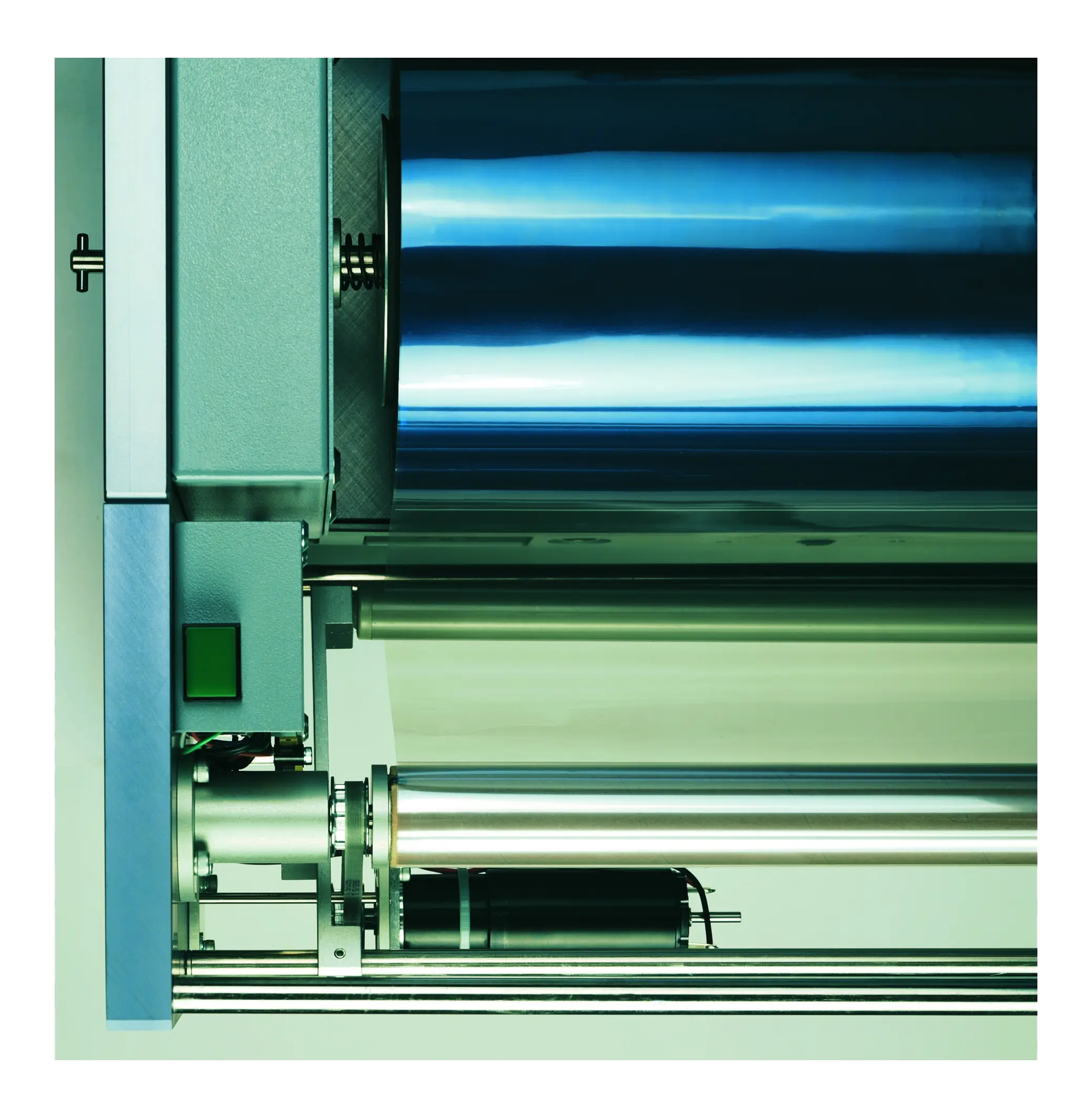
The tape is then pressed onto the upper chamber and the mounting membrane is filled with air to bring the radially symmetrically tensioned tape into contact with the wafer and frame, creating a bubble-free mount.
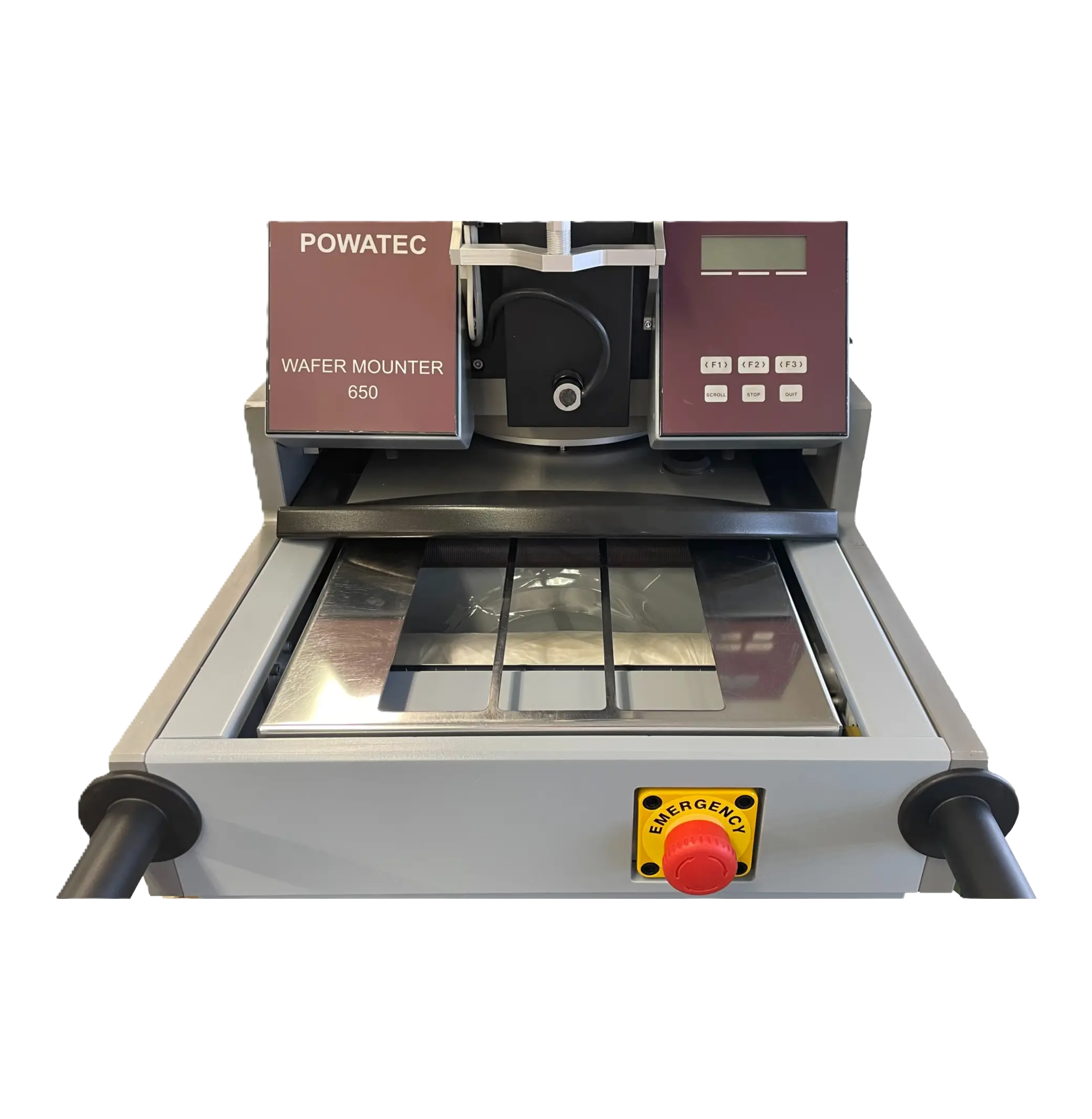
The tape is then automatically cut, and the used tape is collected on a spare roll while the mounted wafer is gently placed in the collection area below the loading table.
By accepting wafers pre-mounted on Gel-Pak carriers, any process flow can be simplified, and handling risks can be drastically reduced. The automated mounting steps reduce the likelihood of operator errors and provide consistent results in an efficient manner.
Features
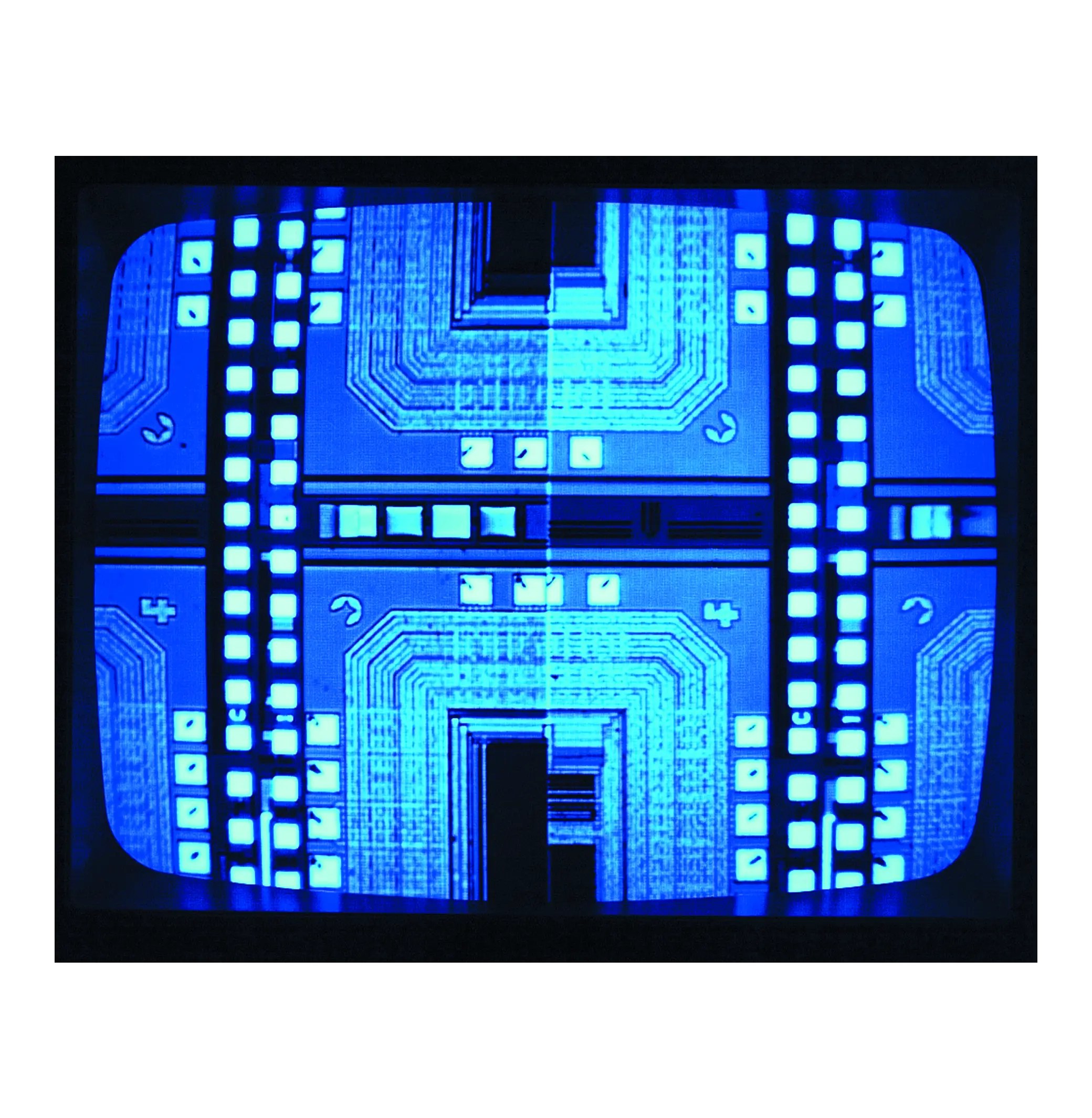
Split-Field Optic
The split-field optical alignment system makes wafer orientation simple and precise during the mounting process. By giving operators a dual-point view of key wafer features, it ensures the wafer is placed on the frame and tape with perfect alignment. This guarantees smooth downstream handling, higher reliability, and consistent results with minimal operator effort.
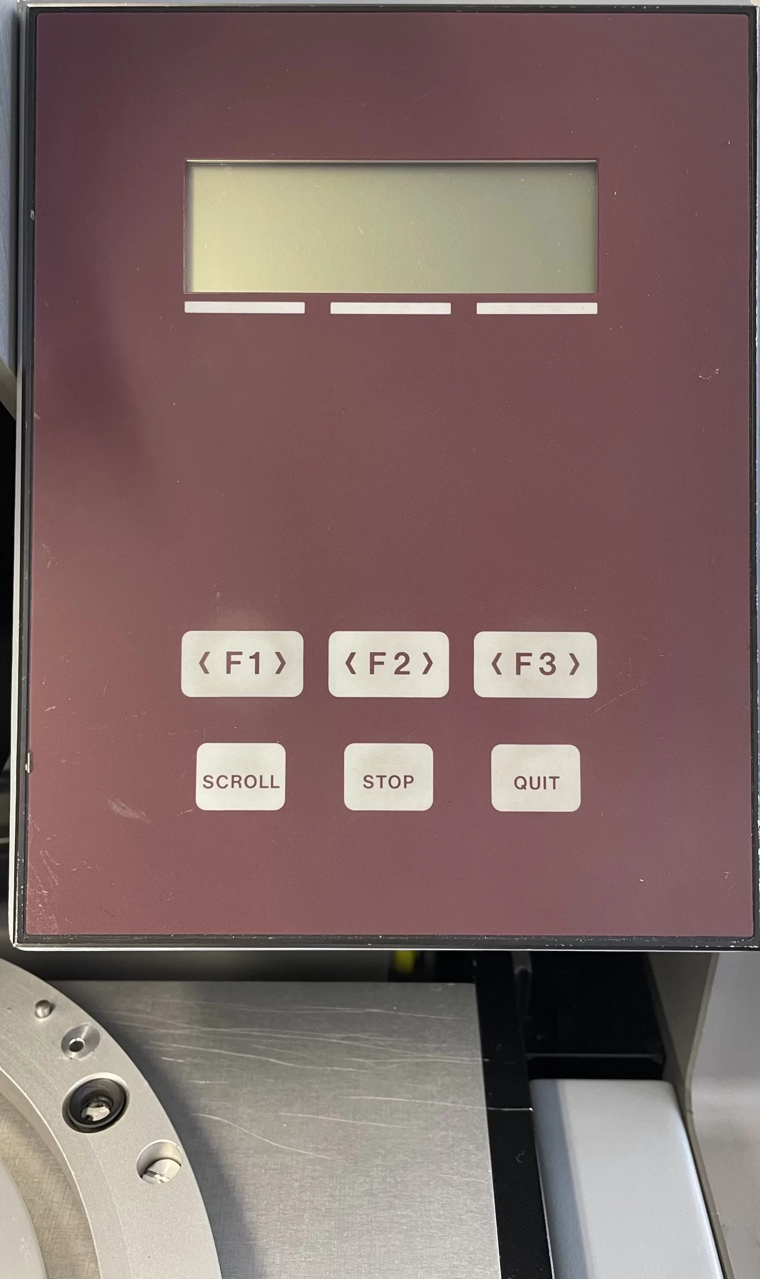
Access Control Lock (ACL)
This optional key lock allows to lock the SET-UP and DEBUG mode. In the SET-UP mode, parameters cannot be altered by unauthorized persons. In DEBUG mode, equipment cannot be operated by unauthorized persons. Those modes can be locked by a key, which can be removed in both locked and unlocked positions.

Removeable Lifting Handles
The WM-650 is fitted with four threaded holes located on the front and rear of the device where carrying handles should be installed. The WM-650 should always be lifted by the handles and always by two people.
Options
PTW (Protection Tape Winder)
When using UV release tapes or tapes with a liner, the use of the PTW is required. It automatically winds up the protective film/liner via a high quality integrated drive. The PTW is mounted on the back of the wafer mounter.
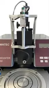
Laser Alignment Tool
This optional module is mounted on the top cover in front of the splitfield optic module. It produces a laser field that includes a single point designating the center of the chuck, and a circular field that aligns with the border of the chuck. It can be used to align wafers or carriers to ensure a concentric placement.
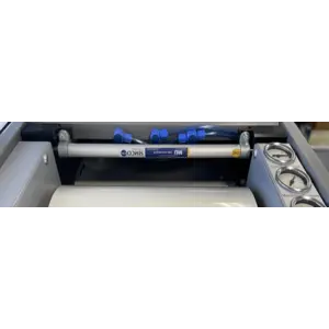
ESD Bar
Unwinding of the film can lead to electrostatic charges. To limit such electrostatic charges it is recommended the use of an ionizing air bar. The bar is installed in the proximity of the tape peel-off point where the greatest electrostatic charges occur. The corresponding control unit is included in the scope of delivery.

Measurement tool for ESD bar
It is recommended to perform a periodic functional check of the ionizing bar.

6″ Dicing Frame Magazine, 25 Slots
25-Slot Magazine, material is solid aluminum

Standard UV Curing System U-200
Suitable for wafers/frames up to Φ8"

Manual Wafer Expander ETM-150
Suitable for wafers/frames up to Φ6"